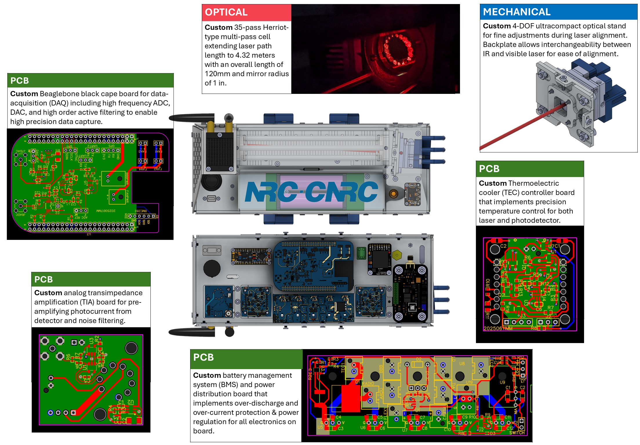
<?xml version="1.0" encoding="utf-8"?><feed xmlns="http://www.w3.org/2005/Atom" ><generator uri="https://jekyllrb.com/" version="3.10.0">Jekyll</generator><link href="https://chasesungit.github.io/Chase-portfolio/feed.xml" rel="self" type="application/atom+xml" /><link href="https://chasesungit.github.io/Chase-portfolio/" rel="alternate" type="text/html" /><updated>2026-09-01T13:07:33+00:00</updated><id>https://chasesungit.github.io/Chase-portfolio/feed.xml</id><title type="html">Portfolio | Chase Sun</title><subtitle>A Portfolio of my mechanical, eletrical, and optical designs and prototypes</subtitle><author><name>Chase Sun</name></author><entry><title type="html">NRC Phantom II - an ultra-light weight, high-precision greenhouse gas sensor</title><link href="https://chasesungit.github.io/Chase-portfolio/electronics-optics/NRC_Phantom_II/" rel="alternate" type="text/html" title="NRC Phantom II - an ultra-light weight, high-precision greenhouse gas sensor" /><published>2026-05-12T00:00:00+00:00</published><updated>2026-05-12T00:00:00+00:00</updated><id>https://chasesungit.github.io/Chase-portfolio/electronics-optics/NRC_Phantom_II</id><content type="html" xml:base="https://chasesungit.github.io/Chase-portfolio/electronics-optics/NRC_Phantom_II/"><![CDATA[<p>Methane is a highly potent greenhouse gas that has been historically poorly measured. There is an increasing demand for portable, sensitive, and cost-effective instruments to better understand the emission of methane and its effect on the changing climate. As a mechatronics engineer at the National Research Council (NRC) between 2021 and 2024, I developed a laser-based methane sensor that allows climate scientists to accurately measure methane emissions with an ultra-light-weight, UAV deployable package.</p>

<h2 id="mechanical-electrical-and-optical-design">Mechanical, Electrical, and Optical Design</h2>
<p><img src="/Chase-portfolio/assets/img/PhantomII/NRC_Design_Diagram.jpg" alt="PhantomII Design Diagram" class="img-breakout" /></p>

<h2 id="physical-assembly">Physical Assembly</h2>
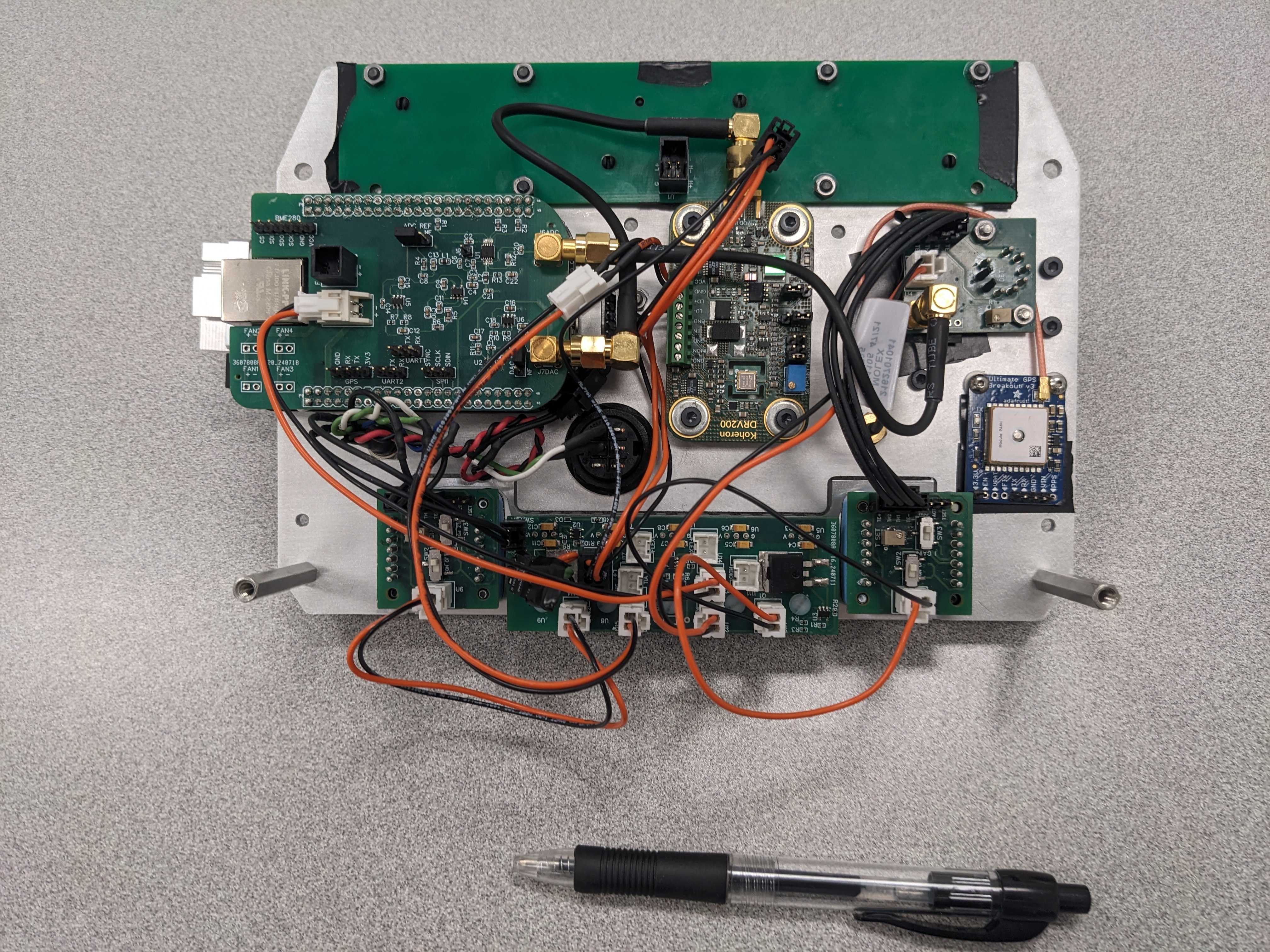
<p><img src="/Chase-portfolio/assets/img/PhantomII/NRC_Physical.jpg" alt="PhantomII Physical package" class="img-wrap-left" />
The physically assembled sensor with slightly extended form factor but identical electronics and optical design. The fully assembled sensor weighs <strong>less than 1kg</strong> and measures at a sensitivity <strong>less than 1 parts-per-billion</strong>, making it easily deployable on mid-sized commercial UAVs.</p>

<h2 id="upgrade-from-previous-design">Upgrade From Previous Design</h2>
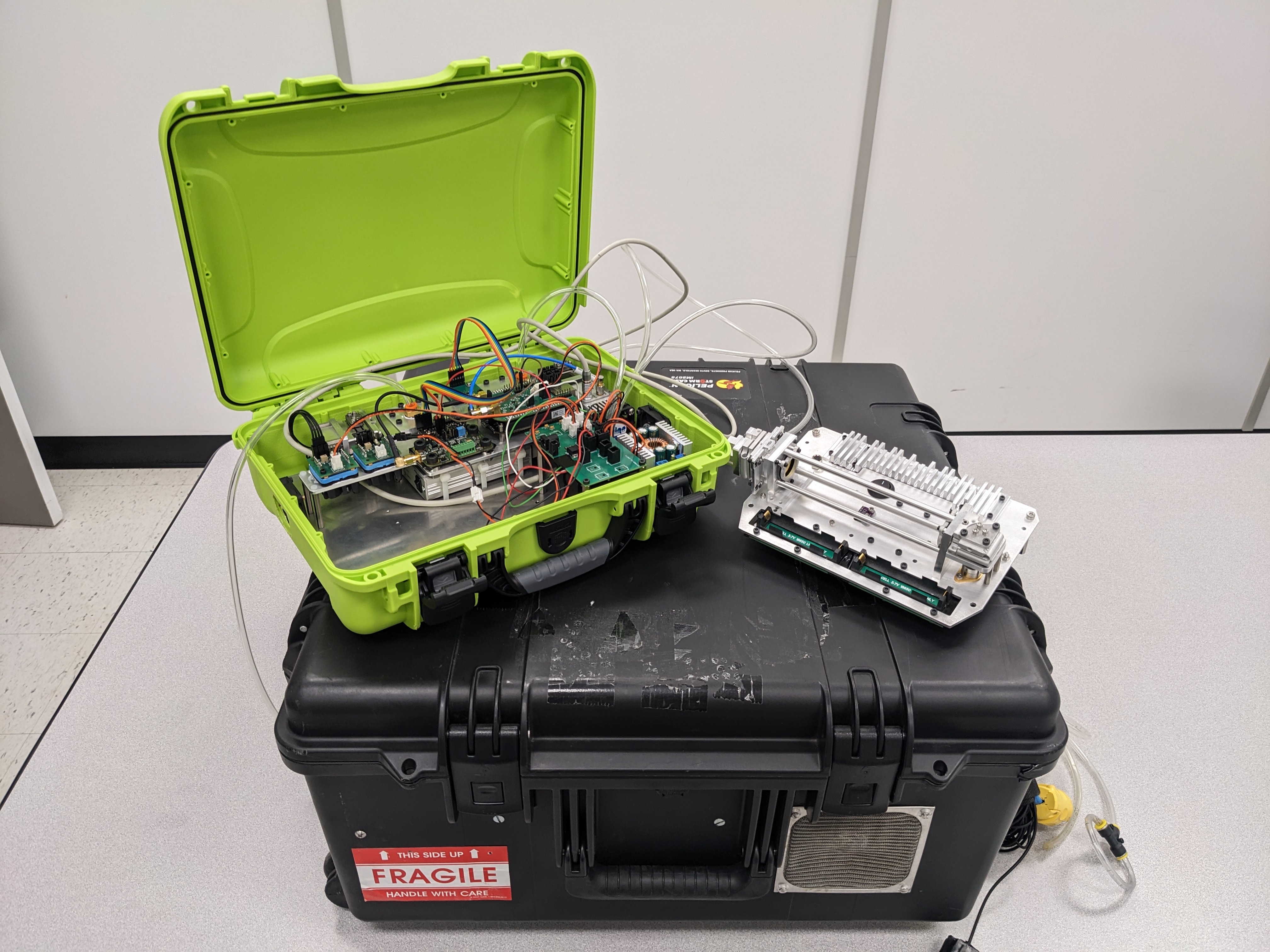
<p><img src="/Chase-portfolio/assets/img/PhantomII/NRC_2sensor_Ontop.jpg" alt="PhantomII Size comparison" class="img-wrap-right" />
Two versions of the sensor, the open cell version Phantom II (right) and close cell version Chameleon (left) sitting on top of the previous NRC methane sensor. The weight was reduced from <strong>25KG</strong> to <strong>3KG</strong> for the closed cell sensor with no sacrifice in sensitivity due to highly custom electronics and embedded software.</p>

<h2 id="deployment">Deployment</h2>
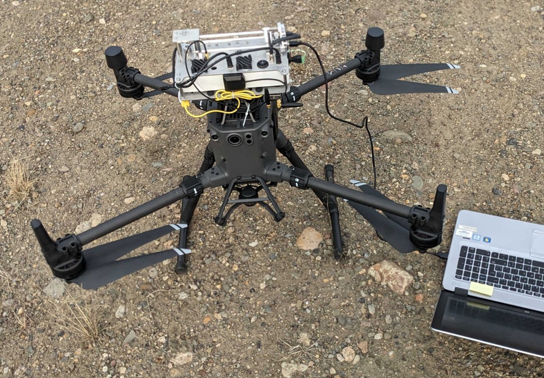
<p><img src="/Chase-portfolio/assets/img/PhantomII/NRC_Deployment.jpg" alt="PhantomII Deployment" class="img-wrap-left" />
The device has been deployed across Canada including near oil &amp; gas facilities in Northern Alberta and the Arctic coast in collaboration with Geological Survey Canada and Environmental &amp; Climate Change Canada to quantify total methane emissions in the country. The sensor seen here is mounted on a DJI Matrice 300 drone as it is prepared to take measurements.</p>

<h2 id="results">Results</h2>
<p><img src="/Chase-portfolio/assets/img/PhantomII/NRC_Results.jpg" alt="PhantomII Deployment" class="img-wrap-right" />
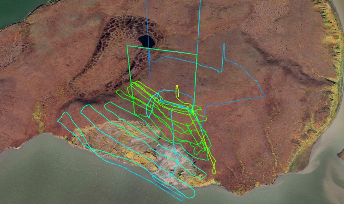
This is the result of a single collection done by the sensor mounted on an UAV measuring methane emissions in the Mackenzie Delta region of Northern Canada. The heatmap is the result of a fusion between GPS data, ambient conditions, and concentration measurement. Higher concentrations are shown in green around the slump site.</p>

<h2 id="associated-publications">Associated Publications</h2>
<p>M. Beattie, <strong>C. Sun</strong>, R. MacLeod, N. Sabourin, P. Morse, J. Corbin, J. Oliaee, “<em>Ultra-Lightweight Mid-IR Methane Sensor for UAV-based measurements</em>”, Journal of Optical Express, Submitted for review</p>

<p>J. Oliaee, R. MacLeod, <strong>C. Sun</strong>, M. Beattie, S. Dallimore, P. Morse, “<em>Measurement of natural methane emissions in the western Canadian arctic using an ultra-lightweight laser spectroscopic sensor aboard a small UAV</em>”, CabCH4 symposium, Ottawa, Canada, May 2024</p>

<p><strong>C. Sun</strong>, J. Oliaee, N. Sabourin, G. Smallwood, “<em>Development of a Lightweight UAV-Mountable Open-Cell Methane Sensor Using Mid-Infrared Tunable Diode Laser Interfaced with a Low-Cost Embedded Platform.</em>” Onboard Sensing, Analysis, and Reporting (OSAR) conference. Riverside, CA, March 2023</p>]]></content><author><name>Chase Sun</name></author><category term="electronics-optics" /><category term="embedded" /><category term="cad" /><category term="optics" /><category term="mechatronics" /><category term="sensing" /><summary type="html"><![CDATA[Methane is a highly potent greenhouse gas that has been historically poorly measured. There is an increasing demand for portable, sensitive, and cost-effective instruments to better understand the emission of methane and its effect on the changing climate. As a mechatronics engineer at the National Research Council (NRC) between 2021 and 2024, I developed a laser-based methane sensor that allows climate scientists to accurately measure methane emissions with an ultra-light-weight, UAV deployable package.]]></summary><media:thumbnail xmlns:media="http://search.yahoo.com/mrss/" url="https://chasesungit.github.io/Chase-portfolio/NRC_Title.jpg" /><media:content medium="image" url="https://chasesungit.github.io/Chase-portfolio/NRC_Title.jpg" xmlns:media="http://search.yahoo.com/mrss/" /></entry><entry><title type="html">GT Miniforklift - a hinge free, under-actuated cable-drvien exoskeleton</title><link href="https://chasesungit.github.io/Chase-portfolio/wearable-robotics/Miniforklift/" rel="alternate" type="text/html" title="GT Miniforklift - a hinge free, under-actuated cable-drvien exoskeleton" /><published>2026-05-11T00:00:00+00:00</published><updated>2026-05-11T00:00:00+00:00</updated><id>https://chasesungit.github.io/Chase-portfolio/wearable-robotics/Miniforklift</id><content type="html" xml:base="https://chasesungit.github.io/Chase-portfolio/wearable-robotics/Miniforklift/"><![CDATA[<p>Workplace injuries are commonplace for high-intensity manual labor workers in the US, especially in environments where heavy duty equipment cannot be used. Exoskeletons have been used to increase the work capacity and reduce injury for the user in this application, but typical designs only target single joints and often incorporate rigid hinges which impede natural motion. As a master’s student in the EPIC lab at Georgia Tech, I am working to design a multi-jointed, completely hinge free exoskeleton to reduce knee &amp; back injuries for manual laborers.</p>

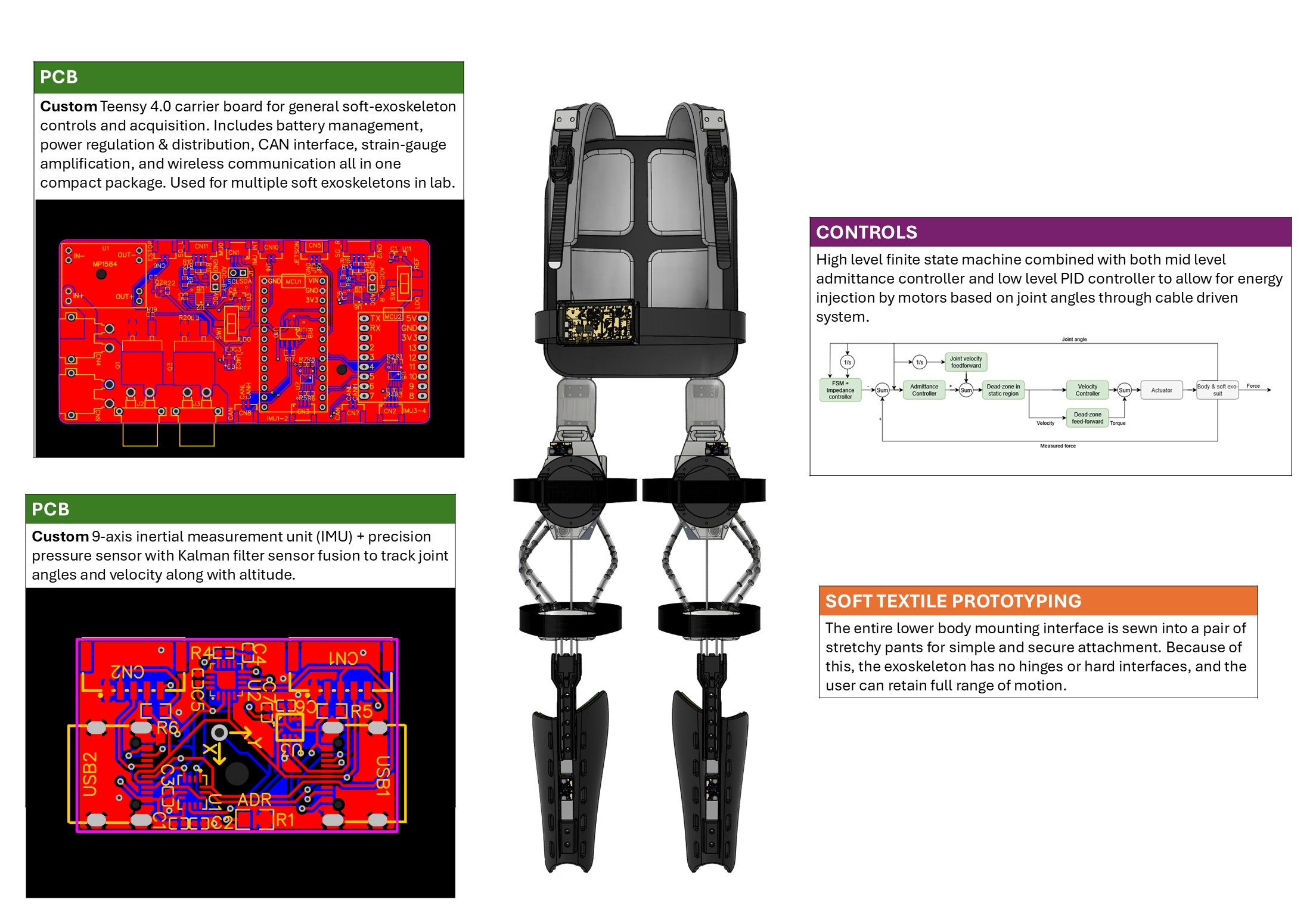
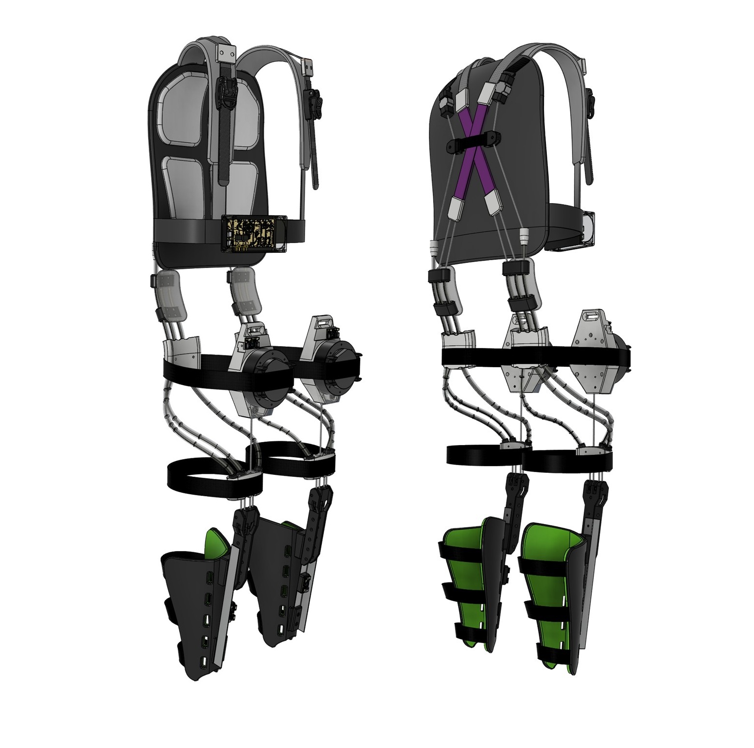
<h2 id="design-overview">Design Overview</h2>
<p><img src="/Chase-portfolio/assets/img/MF3K/EPIC_Design.jpg" alt="Miniforklift Design Diagram" class="img-breakout" /></p>

<h2 id="operating-principle">Operating Principle</h2>
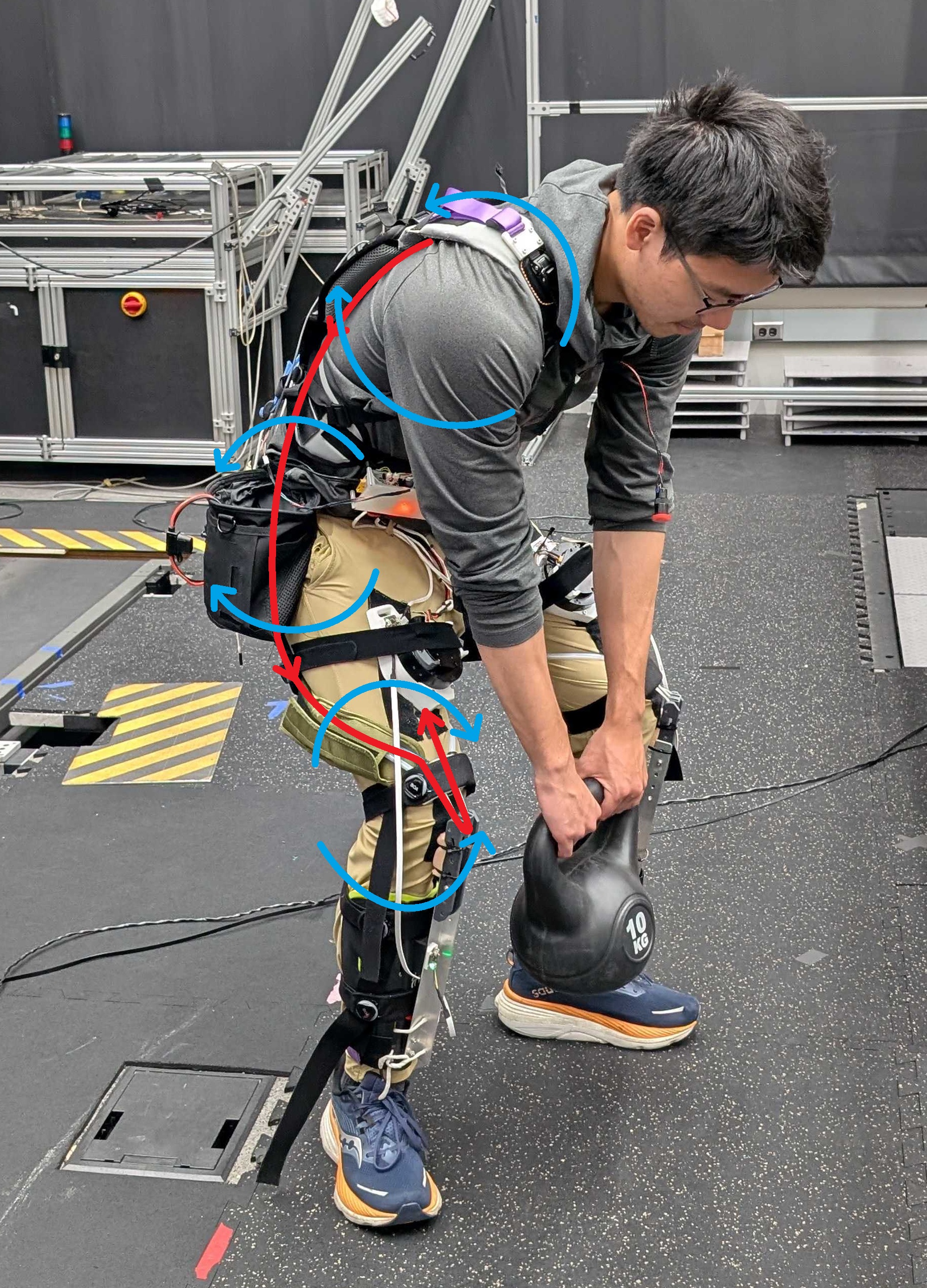
<p><img src="/Chase-portfolio/assets/img/MF3K/EPIC_Lift_Painted.jpg" alt="Miniforklift Operations principle" class="img-wrap-left" />
The soft exoskeleton works by having 2 motors mounted on the thighs to reel in the paracord of the exoskeleton. The cord travels down to the knee and back up, forming a double pulley. It then bypasses the thigh using soft PTFE tubes and attaches at the back, where strain gauges measure the tension in the cord and closes the control loop. When the cord is reeled in, the exoskeleton exerts positive extension work on the 3 joints most involved in lifting motion (knee, hip, and back), and therefore reducing muscle activation and metabolic costs of the user thus reducing the likelihood of injury.</p>

<h2 id="control-loop">Control Loop</h2>
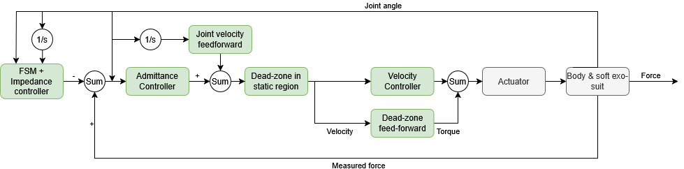
<p><img src="/Chase-portfolio/assets/img/MF3K/EPIC_Control.jpg" alt="Miniforklift Controls" class="img-breakout" />
Since the exoskeleton is actuated by soft paracord, the controller must be adapted to the reality that the actuators can only pull and not push, and that force can only be exerted in 1 direction. The controller hierarchy consists of 3 levels:</p>
<ul>
  <li><strong>High level:</strong> A finite state machine that determines if the user is in lifting or any other activity and outputs the desired tension in the cord.</li>
  <li><strong>Mid level:</strong> An admittance controller that outputs velocity commands to the actuator based on the force required.</li>
  <li><strong>Low level:</strong> A PD controller within the actuator to reach desired velocity.</li>
</ul>

<p>All 3 levels work in series to allow the exoskeleton to near instantaneously  output desired torque on the assisted joints.</p>

<h2 id="cad-render">CAD Render</h2>
<p><img src="/Chase-portfolio/assets/img/MF3K/EPIC_CAD.jpg" alt="Miniforklift CAD" class="img-breakout" /></p>]]></content><author><name>Chase Sun</name></author><category term="wearable-robotics" /><category term="cad" /><category term="controls" /><category term="embedded" /><category term="mechatronics" /><category term="wearable" /><summary type="html"><![CDATA[Workplace injuries are commonplace for high-intensity manual labor workers in the US, especially in environments where heavy duty equipment cannot be used. Exoskeletons have been used to increase the work capacity and reduce injury for the user in this application, but typical designs only target single joints and often incorporate rigid hinges which impede natural motion. As a master’s student in the EPIC lab at Georgia Tech, I am working to design a multi-jointed, completely hinge free exoskeleton to reduce knee &amp; back injuries for manual laborers.]]></summary><media:thumbnail xmlns:media="http://search.yahoo.com/mrss/" url="https://chasesungit.github.io/Chase-portfolio/EPIC_Title.jpg" /><media:content medium="image" url="https://chasesungit.github.io/Chase-portfolio/EPIC_Title.jpg" xmlns:media="http://search.yahoo.com/mrss/" /></entry><entry><title type="html">Chase’s Sixth Sense - An open-source, CAN / BLE capable high-precision IMU for wearable robotics and biomechanics</title><link href="https://chasesungit.github.io/Chase-portfolio/wearable-robotics/SSV2/" rel="alternate" type="text/html" title="Chase’s Sixth Sense - An open-source, CAN / BLE capable high-precision IMU for wearable robotics and biomechanics" /><published>2026-05-10T00:00:00+00:00</published><updated>2026-05-10T00:00:00+00:00</updated><id>https://chasesungit.github.io/Chase-portfolio/wearable-robotics/SSV2</id><content type="html" xml:base="https://chasesungit.github.io/Chase-portfolio/wearable-robotics/SSV2/"><![CDATA[<p>It has always been a challenge to accurately measure the kinematics of human motion with wearable sensors for the purposes of exoskeleton control and machine learning. As a graduate student in the EPIC lab at Georgia Tech, I created a custom 9-axis Inertial measurement unit to perform real time measurements of human motion to replace extremely expensive, aerospace grade IMUs with little to no sacrifice in performance. I also added BLE communications for wireless operation and CAN capabilities to allow for shared communications lines with robotic actuators. The open-source project is currently in development with more detais to be found at: https://github.com/ChaseSunGit/Chases-sixth-sense.</p>

<h2 id="pcb-schematic">PCB Schematic</h2>
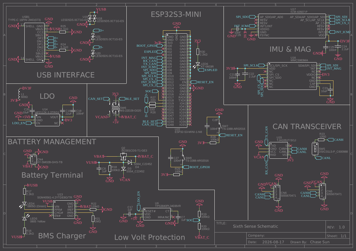
<p><img src="/Chase-portfolio/assets/img/SSv2/Schematic_Sixth-Sense.svg" alt="Sixth Sense PCB" class="img-breakout" />
The Sixth Sense IMU is built on an ESP32S3 Wroom Mini microcontroller on a custom PCB. The two core sensors are:</p>
<ul>
  <li><strong>ICM 42607 Accelerometer + Gyroscope</strong> provides the foundational measurements for Kalman filter sensor fusion using the absolute gravity vector.</li>
  <li><strong>MMC 5983MA Magnetometer</strong> provides the additional North vector for the Kalman filter to accurately calculate Euler yaw.
In addition to these sensors, the PCB also contains:</li>
  <li><strong>TJA 1051T/3/1J CAN Transceiver</strong> allows the sensors to be used in-line with robotic actuators while sharing communications</li>
  <li><strong>Custom Lipo BMS</strong> enables wireless mode by managing the safe charging and discharging of a 1S, 3.7V Lithium polymer battery.</li>
  <li><strong>Power management interface</strong> allows users to switch between BLE wireless and CAN wired modes while always retaining charging, programming, and logging through the UART over USB communication</li>
</ul>

<h2 id="deployment-and-comparison">Deployment and Comparison</h2>
<p><img src="/Chase-portfolio/assets/img/SSv2/SSV2_Deployment.jpg" alt="SSV2 Deployment on subject" class="img-wrap-right" />
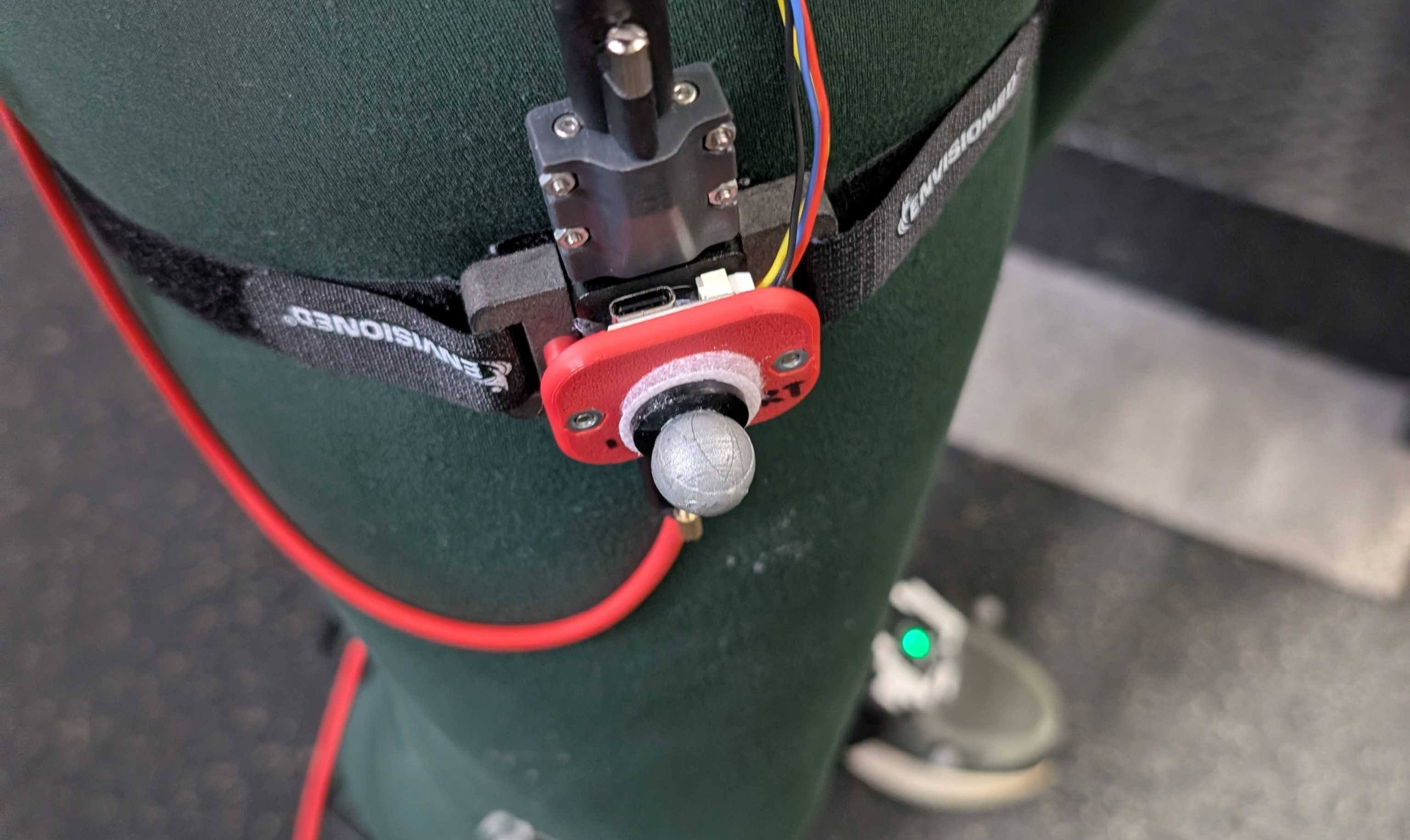
Here, a previous version of the Sixth Sense is mounted along with the Microstrain 3DM-GX5 (Ultra high end IMU costing $2000+) on a test subject along with motion capture dots to track ground truth joint kinematics. The test results are then fed into the EPIC Lab’s machine learning algorithms that predict joint moments from kinematic input.</p>

<h2 id="results">Results</h2>
<p><img src="/Chase-portfolio/assets/img/SSv2/SSV2_Comparison.png" alt="SSV2 comparison" class="img-breakout" />
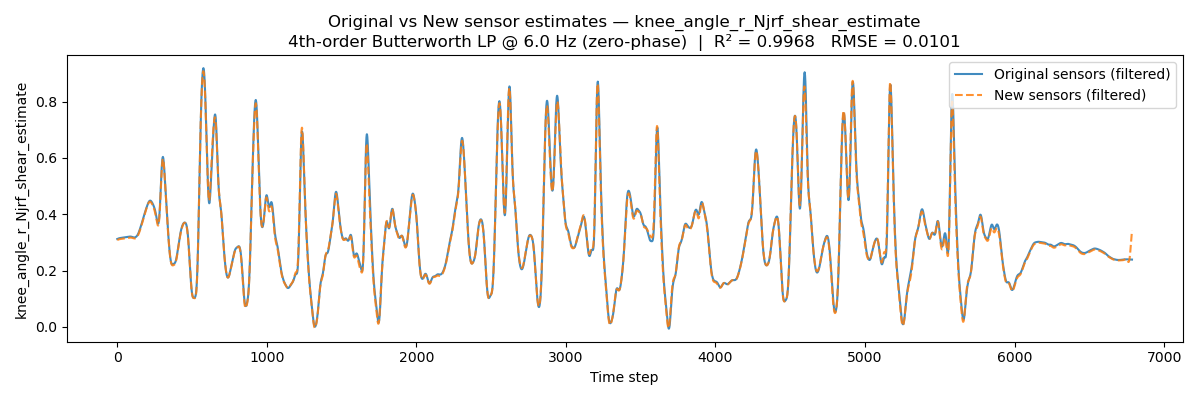
The comparison results in a R-squared of 0.99+, showing near identical output between the two sensors. This allows the lab to replace <strong>$2000+</strong> IMUs with custom PCBs with a unit cost of <strong>$16</strong> with no sacrifice in performance.</p>]]></content><author><name>Chase Sun</name></author><category term="wearable-robotics" /><category term="embedded" /><category term="mechatronics" /><category term="wearable" /><category term="sensing" /><summary type="html"><![CDATA[It has always been a challenge to accurately measure the kinematics of human motion with wearable sensors for the purposes of exoskeleton control and machine learning. As a graduate student in the EPIC lab at Georgia Tech, I created a custom 9-axis Inertial measurement unit to perform real time measurements of human motion to replace extremely expensive, aerospace grade IMUs with little to no sacrifice in performance. I also added BLE communications for wireless operation and CAN capabilities to allow for shared communications lines with robotic actuators. The open-source project is currently in development with more detais to be found at: https://github.com/ChaseSunGit/Chases-sixth-sense.]]></summary><media:thumbnail xmlns:media="http://search.yahoo.com/mrss/" url="https://chasesungit.github.io/Chase-portfolio/CSS_Title.jpg" /><media:content medium="image" url="https://chasesungit.github.io/Chase-portfolio/CSS_Title.jpg" xmlns:media="http://search.yahoo.com/mrss/" /></entry><entry><title type="html">Sonic Chippy - an ultrasonic wind sensor</title><link href="https://chasesungit.github.io/Chase-portfolio/electronics-optics/Ultrasonic-Wind-Sensor/" rel="alternate" type="text/html" title="Sonic Chippy - an ultrasonic wind sensor" /><published>2026-05-09T00:00:00+00:00</published><updated>2026-05-09T00:00:00+00:00</updated><id>https://chasesungit.github.io/Chase-portfolio/electronics-optics/Ultrasonic-Wind-Sensor</id><content type="html" xml:base="https://chasesungit.github.io/Chase-portfolio/electronics-optics/Ultrasonic-Wind-Sensor/"><![CDATA[<p>When I deployed my methane sensor at the Arctic Coast, it was clear that wind plays a huge factor in the gas concentration measured. The commercial cup-and-arrow wind sensor we deployed was expensive, heavy, and very delicate. I decided to create a sonar-based compact wind sensor with the Beaglebone Black single board computer using assembly to program ultra-high frequency data capture.</p>

<h2 id="operating-principle">Operating Principle</h2>
<p><img src="/Chase-portfolio/assets/img/Wind/Wind_Physics.jpg" alt="Ultrasonic Operations principle" class="img-breakout" />
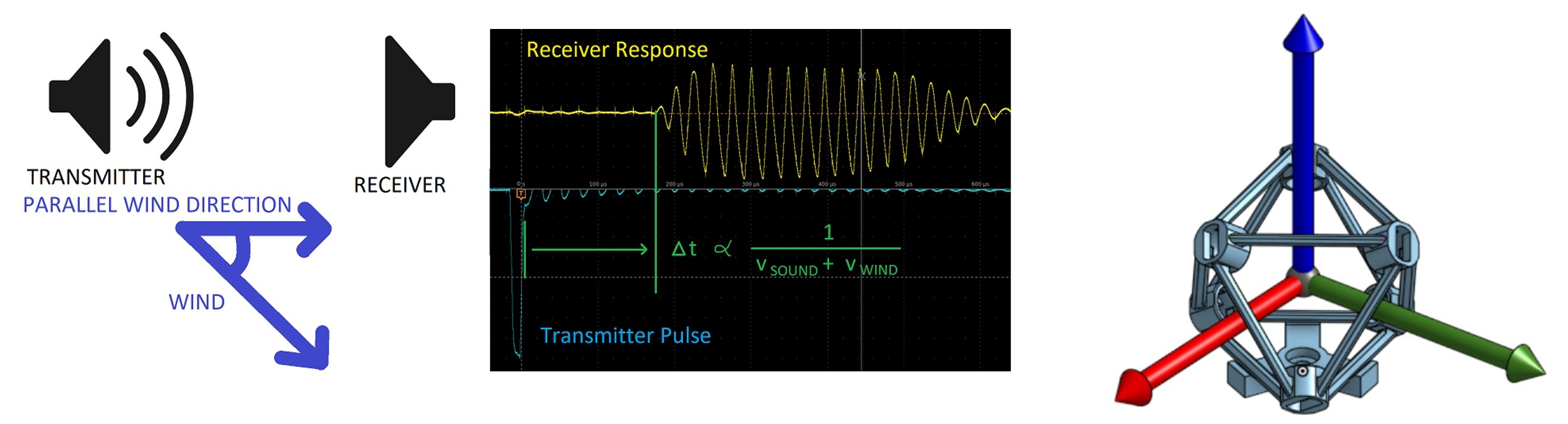
The sonic wind sensor features 3 orthogonal pairs of opposing sonar transceivers where the transmitters are periodically pulsed and the travel time to the receivers are measured. This time is equal to the distance between the transceivers divided by the sum of the speed of sound and the parallel component of the wind. Accurately measuring this time means 3 orthogonal components of wind speed can be calculated.</p>

<h2 id="mechatronics">Mechatronics</h2>
<p><img src="/Chase-portfolio/assets/img/Wind/Wind_Schematic.jpg" alt="Ultrasonic Operations principle" class="img-wrap-left" />
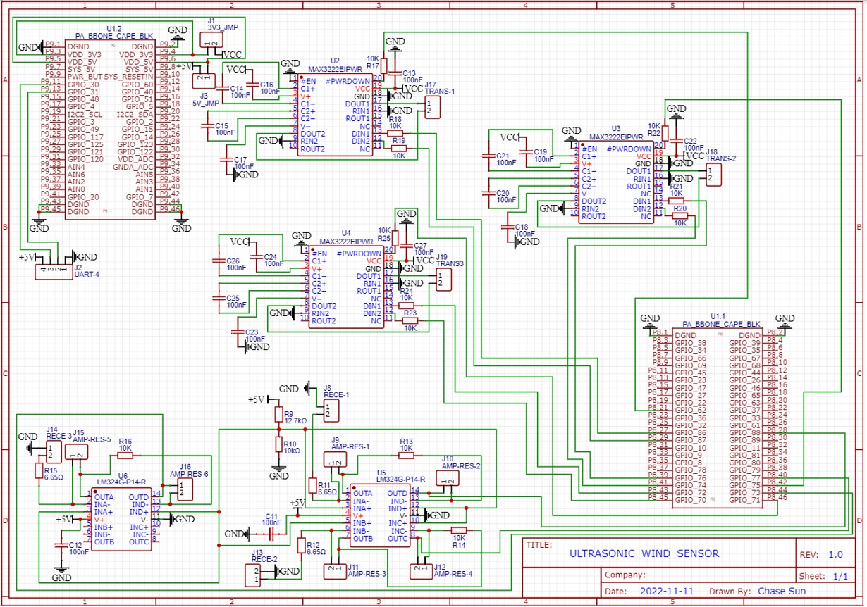
The Beaglebone black SBC is used since it can handle ultra-fast real time operation with assembly. A custom capeboard is used to amplify high-impedance digital signals from the BBB to +-10V low impedance output to power the piezo-electric speakers. The signals from receivers are then read as digital inputs by the BBB with constant polling to precisely calculate time required for the sound to travel. The circuit, along with the high-speed assembly code, allows the sensor to measure 3D wind at <strong>1000Hz</strong>, compared to a traditional wind cup sensor which can only measure 2D wind at ~1Hz.</p>

<h2 id="deployment">Deployment</h2>
<p><img src="/Chase-portfolio/assets/img/Wind/Wind_deployment.jpg" alt="Ultrasonic Operations principle" class="img-breakout" />
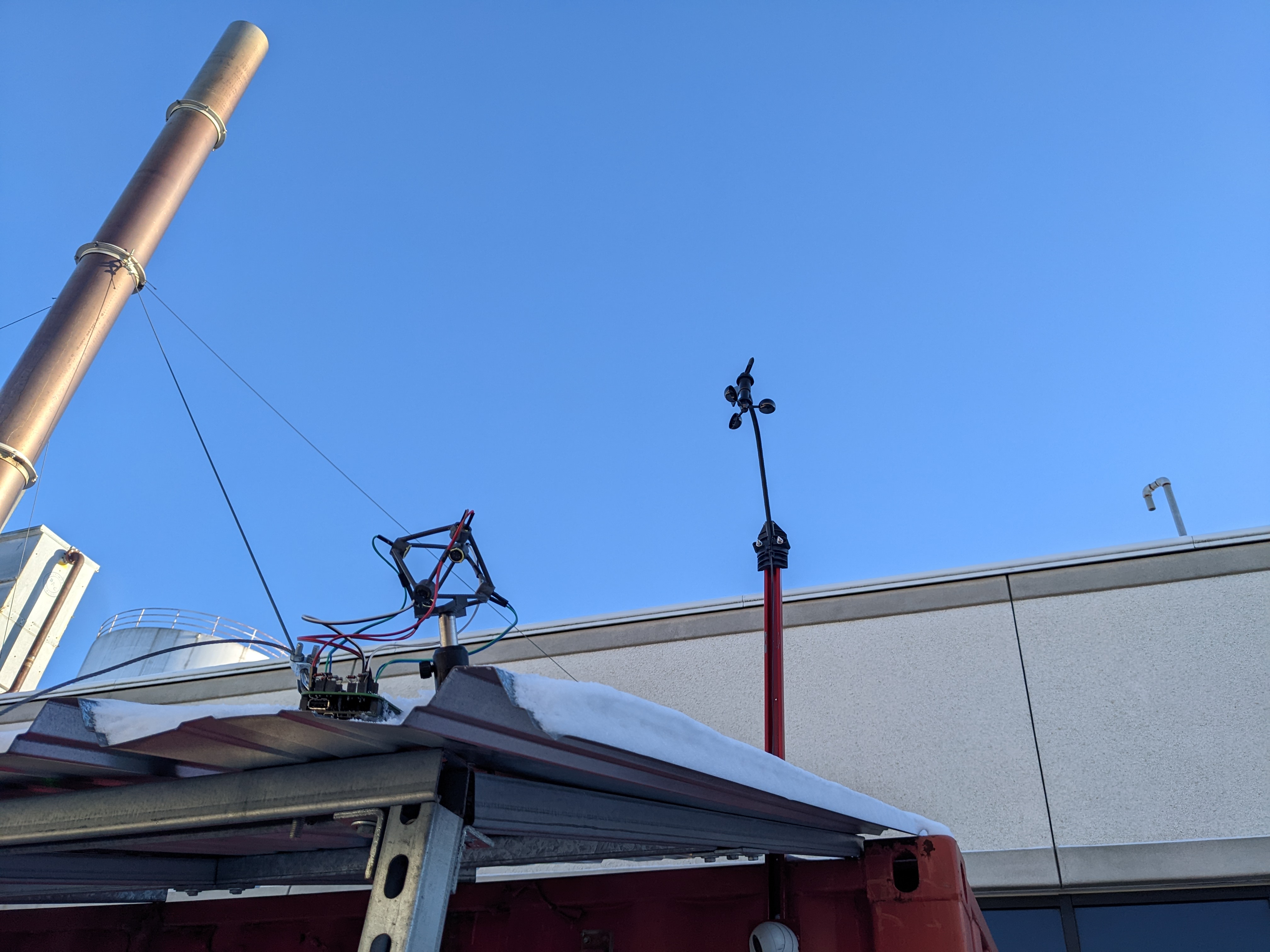
Here the ultrasonic sensor is deployed along with a traditional wind cup sensor to measure the long term stability of the sensor.</p>]]></content><author><name>Chase Sun</name></author><category term="electronics-optics" /><category term="mechatronics" /><category term="embedded" /><category term="sensing" /><summary type="html"><![CDATA[When I deployed my methane sensor at the Arctic Coast, it was clear that wind plays a huge factor in the gas concentration measured. The commercial cup-and-arrow wind sensor we deployed was expensive, heavy, and very delicate. I decided to create a sonar-based compact wind sensor with the Beaglebone Black single board computer using assembly to program ultra-high frequency data capture.]]></summary><media:thumbnail xmlns:media="http://search.yahoo.com/mrss/" url="https://chasesungit.github.io/Chase-portfolio/Wind_Title.jpg" /><media:content medium="image" url="https://chasesungit.github.io/Chase-portfolio/Wind_Title.jpg" xmlns:media="http://search.yahoo.com/mrss/" /></entry><entry><title type="html">NRC PTI - a high-precision Photo-thermal Interferometer</title><link href="https://chasesungit.github.io/Chase-portfolio/electronics-optics/PTI/" rel="alternate" type="text/html" title="NRC PTI - a high-precision Photo-thermal Interferometer" /><published>2026-05-08T00:00:00+00:00</published><updated>2026-05-08T00:00:00+00:00</updated><id>https://chasesungit.github.io/Chase-portfolio/electronics-optics/PTI</id><content type="html" xml:base="https://chasesungit.github.io/Chase-portfolio/electronics-optics/PTI/"><![CDATA[<p>The NRC is developing an instrument that measures black carbon aerosol particles from aircraft engine exhaust. I have designed a sample cell that allows laser excitation and characterization of  aerosol flows through a compact, multichannel cell. This design minimizes the turbulence of the flow and maximizes the path length of the measurement laser.</p>

<h2 id="design-challenge">Design Challenge</h2>
<p><img src="/Chase-portfolio/assets/img/PTI/PTI_Diagram.jpg" alt="PTI Diagram" class="img-wrap-left" />
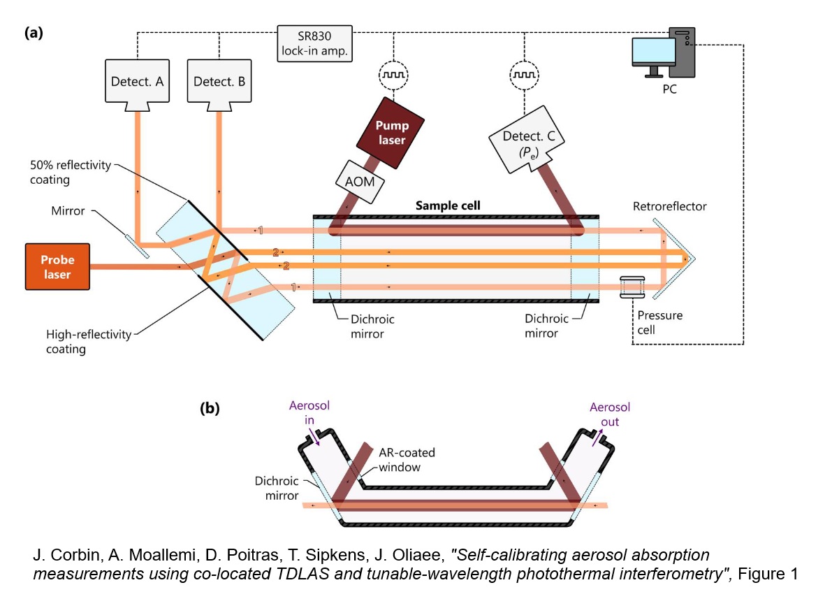
The Photothermal Interferometer (PTI) is used to measure the presence and morphology of black carbon particles as they are significant contributors to climate change world wide. The PTI works by overlaying two laser in the path of flow of carbon particulates, with one laser exciting the particles and the other measuring post-excitation emissions. The challenge for the flow channel I designed is therefore exactly overlapping all 3 elements to enable these measurements.</p>

<h2 id="design-diagram">Design Diagram</h2>
<p><img src="/Chase-portfolio/assets/img/PTI/PTI_Design.png" alt="PTI CAD" class="img-breakout" />
To overlap all elements, I designed a U-shaped channel for air flow carrying carbon particles with a window at the bottom sealed by a dichroic mirror. This dichroic allows the 632nm probe laser (red) to pass through while reflecting the 760nm heating laser (orange) directly into the same path and exits on the other side. The heating laser is injected at Brewster’s angle to minimize reflection and maximize power.</p>

<h2 id="computational-fluid-dynamics">Computational Fluid Dynamics</h2>
<p><img src="/Chase-portfolio/assets/img/PTI/PTI_CFD.jpg" alt="PTI CFD" class="img-breakout" />
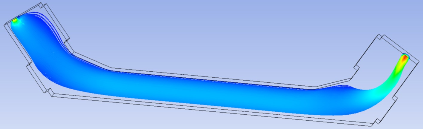
To validate the design in simulation, I performed computational fluid dynamics simulations with ANSYS Fluent to see the path of travel of particles seeded into the stream. Since the design required that the particles stay on the same path of the laser, I ensured that the flow across the channel was maximally laminar through modifying the cross-section geometry of the channel.</p>

<h2 id="associated-publication">Associated Publication</h2>
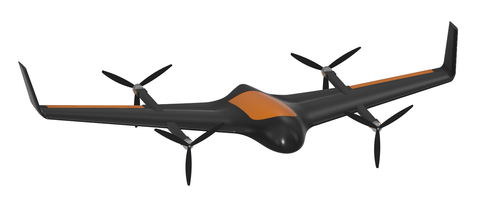
<p>J. Corbin, A. Moallemi, D. Poitras, T. Sipkens, J. Oliaee (07 Mar 2025): “<em>Self-calibrating aerosol absorption measurements using co-located TDLAS and tunable-wavelength photothermal interferometry</em>”, Aerosol Science and Technology</p>]]></content><author><name>Chase Sun</name></author><category term="electronics-optics" /><category term="cad" /><category term="cae" /><category term="optics" /><category term="sensing" /><summary type="html"><![CDATA[The NRC is developing an instrument that measures black carbon aerosol particles from aircraft engine exhaust. I have designed a sample cell that allows laser excitation and characterization of aerosol flows through a compact, multichannel cell. This design minimizes the turbulence of the flow and maximizes the path length of the measurement laser.]]></summary><media:thumbnail xmlns:media="http://search.yahoo.com/mrss/" url="https://chasesungit.github.io/Chase-portfolio/PTI_Title.jpg" /><media:content medium="image" url="https://chasesungit.github.io/Chase-portfolio/PTI_Title.jpg" xmlns:media="http://search.yahoo.com/mrss/" /></entry><entry><title type="html">Peregrine 2 - a blended wing VTOL UAV</title><link href="https://chasesungit.github.io/Chase-portfolio/cad-cae/BWB_UAV/" rel="alternate" type="text/html" title="Peregrine 2 - a blended wing VTOL UAV" /><published>2026-05-07T00:00:00+00:00</published><updated>2026-05-07T00:00:00+00:00</updated><id>https://chasesungit.github.io/Chase-portfolio/cad-cae/BWB_UAV</id><content type="html" xml:base="https://chasesungit.github.io/Chase-portfolio/cad-cae/BWB_UAV/"><![CDATA[<p>Blended wing body (BWB) aircraft designs have been shown to have better fuel efficiency and cargo carrying capacity than comparable conventional aircraft. The goal of my capstone project was to design a BWB UAV and manufacture it entirely with 3D printing. For this project, I served both as the <strong>project manager</strong> of a team of 22 students as well as the <strong>lead CAD designer</strong>, primarily creating the wing geometry for assembly, simulation, and manufacturing.</p>

<h2 id="surface-modelling">Surface Modelling</h2>
<p><img src="/Chase-portfolio/assets/img/BWB/BWB_Surface.jpg" alt="Peregrine wing geometry" class="img-breakout" />
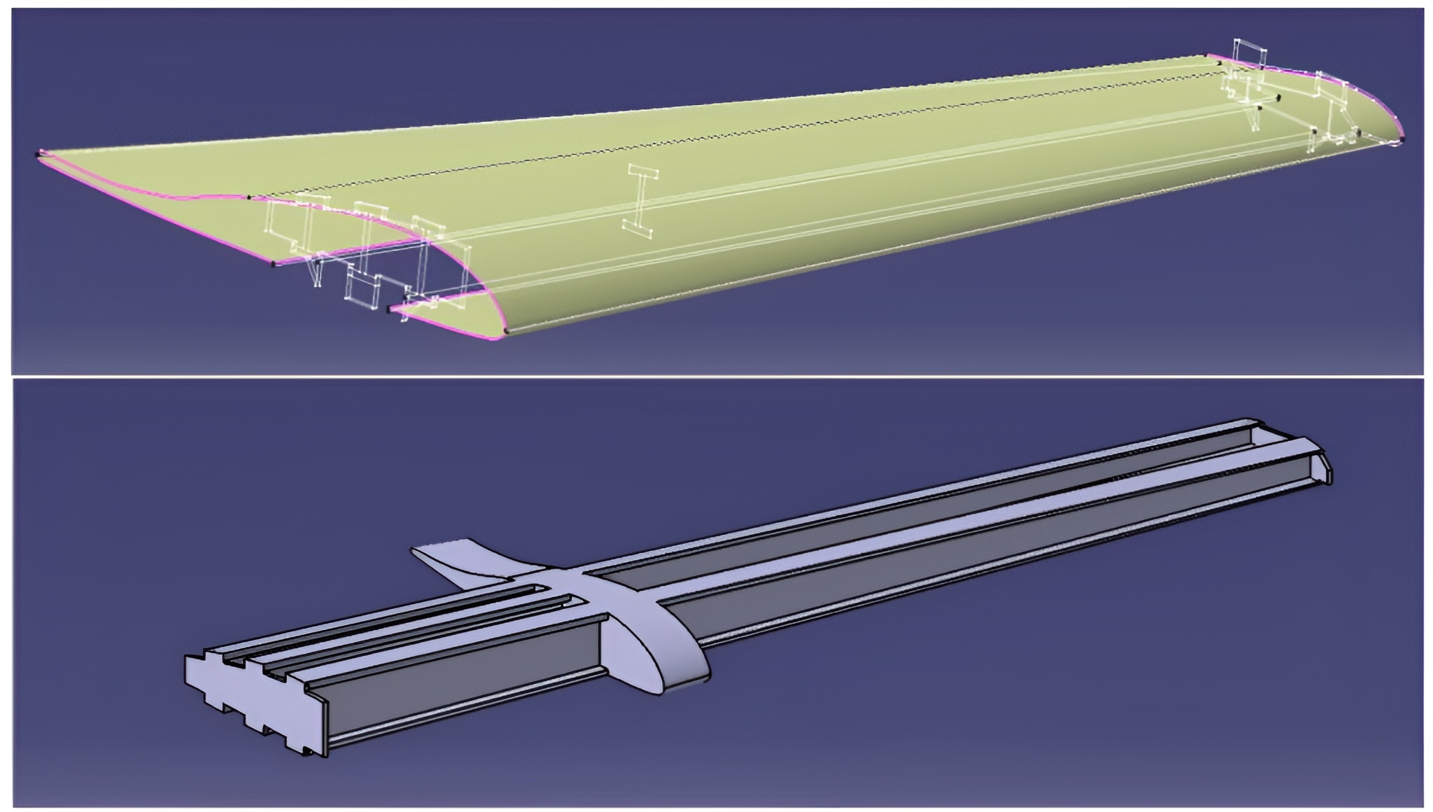
The model of the UAV is based on the Skywalker X-8 Aerodynamic profile modified to be 3D printable. The challenge is that the airframe is very large (a wing span of 2 meters) and therefore parts had to be printed in segments and assembled. The CAD work primarily consists of using surface lofts to match the shape of the X-8 airfoil while creating 3D printable internal spars and ribs.</p>

<h2 id="vertical-takeoff-and-landing">Vertical Takeoff and Landing</h2>
<p><img src="/Chase-portfolio/assets/img/BWB/BWB_CAD.jpg" alt="Peregrine wing CAD" class="img-wrap-left" />
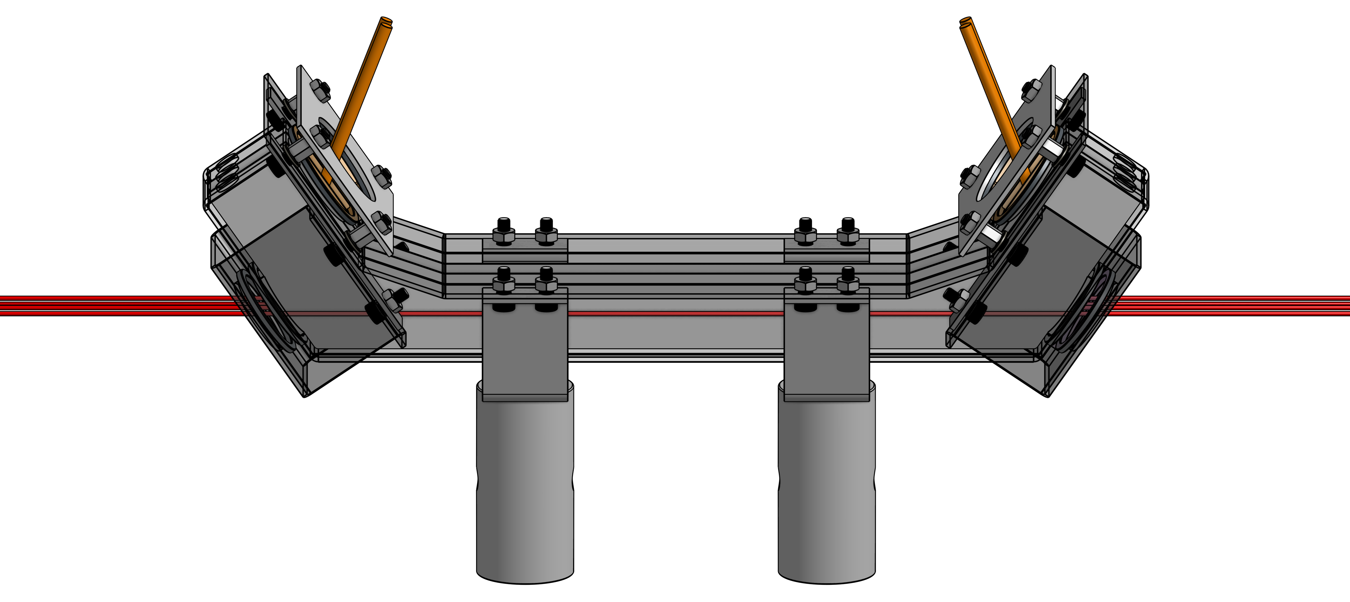
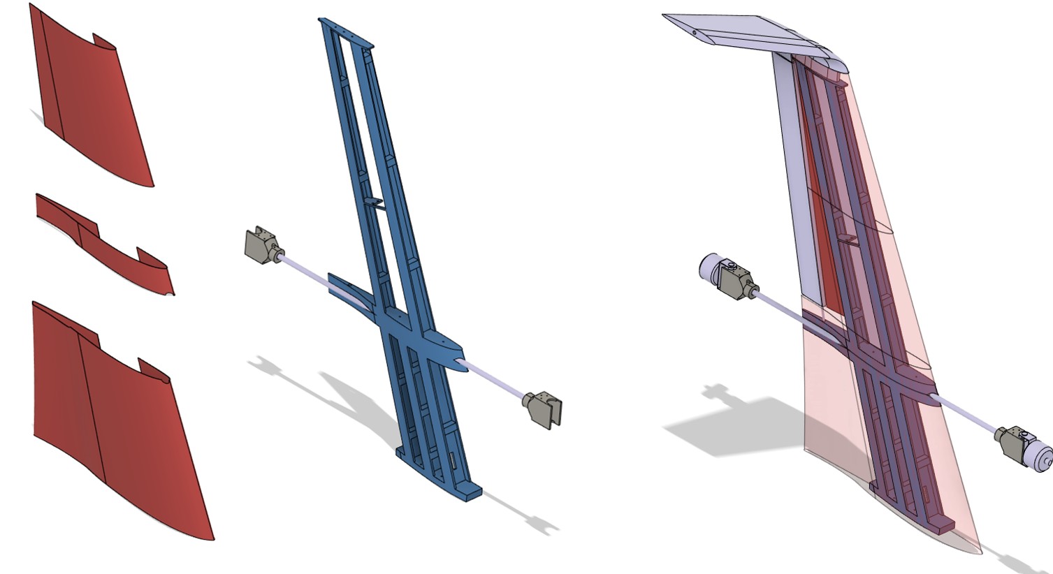
Another major design challenge was the requirement for vertical takeoff and landing (VTOL) capabilities. We incorporated carbon rods which attaches to actuators on both ends of the wing, mounted on servos which allows the rotors to tilt during flight.</p>

<h2 id="cad-render">CAD Render</h2>
<p><img src="/Chase-portfolio/assets/img/BWB/BWB_Full_CAD.png" alt="Peregrine CAD" class="img-breakout" /></p>]]></content><author><name>Chase Sun</name></author><category term="cad-cae" /><category term="cad" /><category term="cae" /><summary type="html"><![CDATA[Blended wing body (BWB) aircraft designs have been shown to have better fuel efficiency and cargo carrying capacity than comparable conventional aircraft. The goal of my capstone project was to design a BWB UAV and manufacture it entirely with 3D printing. For this project, I served both as the project manager of a team of 22 students as well as the lead CAD designer, primarily creating the wing geometry for assembly, simulation, and manufacturing.]]></summary><media:thumbnail xmlns:media="http://search.yahoo.com/mrss/" url="https://chasesungit.github.io/Chase-portfolio/BWB_Title.jpg" /><media:content medium="image" url="https://chasesungit.github.io/Chase-portfolio/BWB_Title.jpg" xmlns:media="http://search.yahoo.com/mrss/" /></entry><entry><title type="html">Wall-E 2.0 - an automated street sweeper robot design</title><link href="https://chasesungit.github.io/Chase-portfolio/cad-cae/SSP/" rel="alternate" type="text/html" title="Wall-E 2.0 - an automated street sweeper robot design" /><published>2026-05-06T00:00:00+00:00</published><updated>2026-05-06T00:00:00+00:00</updated><id>https://chasesungit.github.io/Chase-portfolio/cad-cae/SSP</id><content type="html" xml:base="https://chasesungit.github.io/Chase-portfolio/cad-cae/SSP/"><![CDATA[<p>The Carleton University Design League hosted a designathon in which teams of 4 students compete to design and model an eco-friendly autonomous street sweeper. I participated with 3 friends and took on the role of team leader and waste collection system designer. Our goal was to create a robot that can collect and sort garbage while operating in the harsh winter conditions of Ontario. To fit the challenge requirements, we maximized our use of recyclable materials for this robot’s construction. We had 36 hours to complete our design and present our work to a panel of judges.</p>

<h2 id="design">Design</h2>
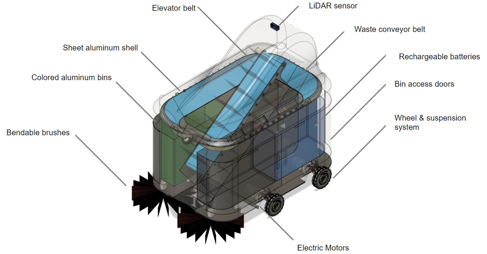
<p><img src="/Chase-portfolio/assets/img/SSP/SSP_Design.jpg" alt="SSP design" class="img-wrap-left" />
The Wall-E Jr robot is designed with principles of sustainable engineering in mind, which means it uses primarily recyclable materials (aluminum and rubber) and is simple to produce, assemble, and repair. It is designed to automatically drive around the streets of Ontario and collect and sort trash into four categories.</p>

<h2 id="streetsweeper-operation">Streetsweeper Operation</h2>
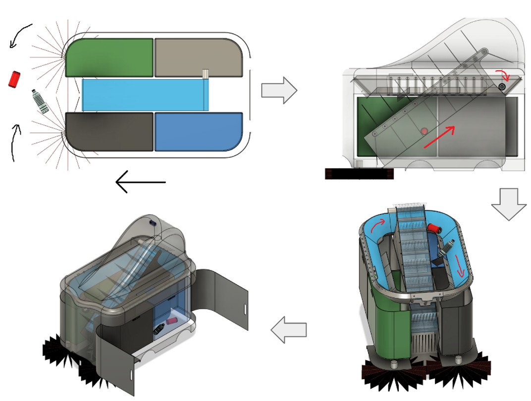
<p><img src="/Chase-portfolio/assets/img/SSP/SSP_Operation.jpg" alt="SSP operation" class="img-wrap-right" /></p>
<ul>
  <li>Garbage is swept into the central chamber of the robot as it moves forward along a sidewalk</li>
  <li>The elevator brings the garbage up and drops it onto the sorting conveyer belt</li>
  <li>The garbage is then passed through 4 sensors that determines the category of the item (plastic, paper, compost, and non-recyclables) and drops them into the appropriate bins</li>
  <li>The garbage can be taken out once the robot returns to home station to recharge</li>
</ul>]]></content><author><name>Chase Sun</name></author><category term="cad-cae" /><category term="cad" /><summary type="html"><![CDATA[The Carleton University Design League hosted a designathon in which teams of 4 students compete to design and model an eco-friendly autonomous street sweeper. I participated with 3 friends and took on the role of team leader and waste collection system designer. Our goal was to create a robot that can collect and sort garbage while operating in the harsh winter conditions of Ontario. To fit the challenge requirements, we maximized our use of recyclable materials for this robot’s construction. We had 36 hours to complete our design and present our work to a panel of judges.]]></summary><media:thumbnail xmlns:media="http://search.yahoo.com/mrss/" url="https://chasesungit.github.io/Chase-portfolio/SSP_Title.jpg" /><media:content medium="image" url="https://chasesungit.github.io/Chase-portfolio/SSP_Title.jpg" xmlns:media="http://search.yahoo.com/mrss/" /></entry><entry><title type="html">About me</title><link href="https://chasesungit.github.io/Chase-portfolio/about/About_Me/" rel="alternate" type="text/html" title="About me" /><published>2026-05-05T00:00:00+00:00</published><updated>2026-05-05T00:00:00+00:00</updated><id>https://chasesungit.github.io/Chase-portfolio/about/About_Me</id><content type="html" xml:base="https://chasesungit.github.io/Chase-portfolio/about/About_Me/"><![CDATA[<p>Hello! My name is Chase, and I am an engineer and a maker. At age six, I knew that it was my dream to become an inventor as I frequently stole cardboard boxes from my grandma’s recycling bin to make robot models and gadgets. Today, I am very grateful to be living that dream, not only working on cutting edge engineering designs, but also teaching the next generation of inventors how to turn their cool ideas into reality. I am never afraid to explore new areas of interest, and have acquired a very diverse skill-set in circuits, software, optics, and of course, mechanical engineering throughout my work and research experiences. I am particularly skilled in CAD and prototyping, and have always loved building on top of what I learned through personal engineering projects.</p>

<p>Outside of work, I am a big fan of combat sports, and I compete as a boxer and a mixed martial artist. You will also find me running, hiking, and rock climbing when I want to take a break from fighting. I also spend a lot of my free time volunteering in areas of engineering education and outreach, where I teach all sorts of young engineers from 5th graders to PhD students on how to design and make things they are excited about.</p>

<p>I hope that this portfolio gives you a taste of not only my work and skill-set, but also my passion and personality as well. Thanks for reading and have a great day!</p>

<p>Here’s me fighting to raise money for St Jude Children’s Hospital.
<img src="/Chase-portfolio/assets/img/AM/AM_Boxing.jpg" alt="Boxing" class="img-breakout" /></p>]]></content><author><name>Chase Sun</name></author><category term="about" /><category term="About" /><summary type="html"><![CDATA[Hello! My name is Chase, and I am an engineer and a maker. At age six, I knew that it was my dream to become an inventor as I frequently stole cardboard boxes from my grandma’s recycling bin to make robot models and gadgets. Today, I am very grateful to be living that dream, not only working on cutting edge engineering designs, but also teaching the next generation of inventors how to turn their cool ideas into reality. I am never afraid to explore new areas of interest, and have acquired a very diverse skill-set in circuits, software, optics, and of course, mechanical engineering throughout my work and research experiences. I am particularly skilled in CAD and prototyping, and have always loved building on top of what I learned through personal engineering projects.]]></summary><media:thumbnail xmlns:media="http://search.yahoo.com/mrss/" url="https://chasesungit.github.io/Chase-portfolio/AM_Title.jpg" /><media:content medium="image" url="https://chasesungit.github.io/Chase-portfolio/AM_Title.jpg" xmlns:media="http://search.yahoo.com/mrss/" /></entry></feed>